
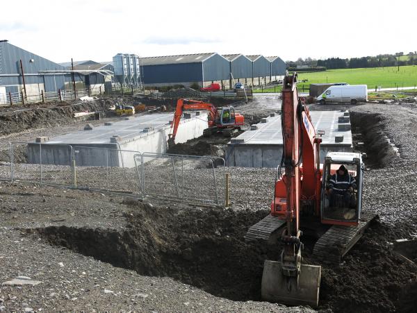
I recently visited Teagasc Grange to meet engineer JJ Lenehan and to view a newly-built, large tank on the research farm. The tank is for a new suckler house. I also met Darragh King, who was doing all the groundwork and concreting. He manages King Concrete, based at Kilmoon, Ashbourne, Co Meath.
Picture one
When I called, the tanks were in place and ready for backfilling. There are two ‘double’ tanks with space in the middle which will eventually become the shed’s centre feed passage. Each tank is 20.4m (67ft) long and 7.3m (24ft) wide. Each is divided in half – along its length – by a spine wall.
The tanks have been given 28 days for the concrete to cure prior to placing slats and backfilling. The Department of Agriculture building specifications say not to fit slats until backfilling has taken place – this is to give safety for the trucks delivering the slats. However, most building contractors like to lay the slats first and are equipped to do so.
Picture two
Dealing first with the outside of the tanks, the first thing I want to point out is the pre-cast beam at the end of the slats to support the shed end wall. JJ said that this is a better arrangement than simply building the shed end wall on a gang slat. Slats have a finite working life and eventually have to be replaced. If the end wall is sitting on a gang slat, it is impossible to remove the gang slat from under the wall. The problem won’t arise here. All the slats can be replaced without having to go near the end wall and the precast beam, which will not need to be replaced. Placing beams under end walls has been a requirement of the Department of Agriculture specifications for over 10 years. The beam is steel reinforced and its depth matches the adjacent gang slat. Beside the beam, we see a three-rib gang to fit the gap.
Meanwhile, there are agitation points at just one end of the tanks as straw-bedded calving pens will be located at the other end of the shed. For any tank over 16m in length, the recommendation from the Department of Agriculture is for agitation points at both ends. This is to ensure adequate agitation is possible.
To ensure adequate agitation of these tanks, an additional measure will be put in place.
A plastic pipe will be run along the inside wall of the tank to allow slurry to be pumped to the opposite end of the tank from the agitation points. A circular opening has been cast in the manhole slat to accommodate the slurry re-circulating pipe which will be fed by the slurry agitation pump.
Standard safety manhole covers are fitted at the agitation points. These will be used for agitation only – not for emptying. A second circular opening has been cast to allow a fixed tanker filler pipe to be fitted. This pipe will protrude above the tank lid and be fitted with a pipe coupling to allow connection to the slurry tanker fill valve via a short length of pipe.
Picture three
‘’There will be safety advantages,’’ said JJ. ‘‘The pipe and coupling will be permanently in place. It is safer than leaving the conventional tanker filler pipe in place at the agitation point when many operators leave the safety manhole cover in the open position while going out to the field.’’
Picture four
At the other end, the tank end wall has been kept 100mm lower leaving a gap under the slats. Bedded calving pens will be built here and urine and slurry will be allowed drain through this opening into the tank.
Pictures five & six
Each of the shed’s two tanks are 7.3m wide and have two external walls and a spine wall in the centre. The spine wall serves two functions. It helps slurry circulate during agitation and it also supports slats allowing tanks be wider than would be possible if they had to span the full width of a tank. The maximum length of slat being made for farm use is 5m (16ft). Here, the tank is covered by two rows of 3.8m (12ft 6in) slats.
The gang slats are sitting level and straight on the walls with no rocking. In the centre of the picture, sitting over the spine wall, we can see metal stands for the posts for pen barriers/gates. JJ explained that posts for pens and barriers can be easily bolted to these stands which are very secure. ‘‘In addition, they won’t interfere with the changing of slats when the time eventually comes to do so.’’ See Picture 9.
Picture seven
We see the external walls on left and right and the spine wall in the middle. All of the walls are built to the Department specification. There is steel mesh under the full floor area as the external tank walls are more than 4m apart.
The spine wall is 300mm wide. This is to ensure that the end of the slats coming from left and right have a wide enough bearing (seating) to be secure. The Department recommendation is that 150mm of slat end is sitting on wall. As the wall supports two rows of slats, a wall width of 300mm is therefore necessary. The spine wall is reinforced on both sides. The external walls support one slat end and are 225mm wide.
Picture eight
The openings at the ends of the spine wall allow slurry to circulate and ensure that the slurry is at the same level on each side of the centre spine wall. In the design of these tanks, the opening is equivalent to the width of the slats.
Picture nine
We see that the bottom of the H-iron is bolted into the spine wall. The wall has been recessed slightly so that the frame sits an inch below the slats, not touching them. This gap will be filled with mortar before the tank is used.
)


SHARING OPTIONS